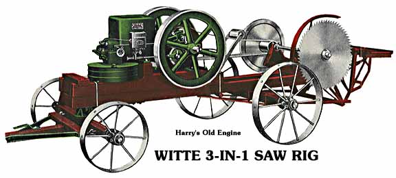
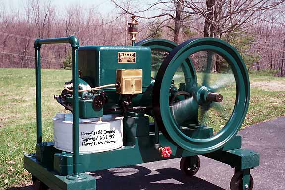
Witte 5 Horsepower Throttle Governed Farm Engine
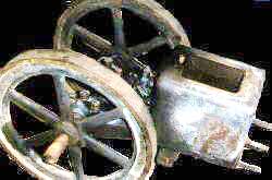
Here is the old Witte as found in a disassembled condition. I started by salvaging the wooden skid frame and cleaning up the head and magneto. The small bowl idle jet was stuck and the knob was missing, but I freed it up and replaced the knob.
It sure was a back breaker lifting the crank and flywheel into place. If BOTH flywheels had been on the crankshaft, I would have needed a winch to lift it. The Witte is now up and running with everything all restored and back together with the exception of its kerosene tank. I've been able to run it with gasoline in the start-up bowl of the carb.
Starting it is quite hard, but once it's running, it runs like a champ. It has excellent compression and I'm able to adjust the fuel mix somewhere between backfiring (too lean) and smoky exhaust (too rich). I have found that if I put the spark selector on retard, it pretty much wants to stall out. (Just the same as its stubbornness on retarded starting.) If the spark is put on regular advance, it goes right back to running like a champ. (Keep in mind, this is my FIRST old engine.)
I suspect that the WICO magneto is weaker on retard than on full advance. The timing is set ok with the mark on the flywheel. I did find that for a TYPE 1 trigger, they recommend 1/16" point gap and for a TYPE 2 trigger - 3/32" gap. Mine is more like 3/32" with a TYPE 1.
I have tried two different WICO's and they both perform weakly on the Witte. In fact, the second one is from a Jaeger that while running on the Jaeger shoots out a big spark. The Jaeger is a TYPE 2 trigger. Seems like the armature has to drop down in a hurry or you don't get much spark.
Spring is here! Well, sort of - we had a few snow flurries this evening. Anyhow, I pulled the Witte out for a go at it and ran back into my same magneto problem. I've accumulated a few more engines since first working on the Witte so with none less than FOUR Wico's to choose from, I spread them across the workbench and proceeded to take measurements.
I checked the point break gap tolerance and found them all much greater than the 1/16th inch so I brought this into a reasonable distance. Then I measured resistance at various terminals and found two with open secondaries, all primaries ok, and the Witte original mag had an EXTREMELY leaky condensor. One of the lot tested reasonably close to what I expected to find, so I installed it in the original Witte and put the covers back together. Sure enough - SPARKS!!!
I should have learned about capacitor reliability by now as I had a similar problem on my Ford 2N. In fact, it might be wise to learn as much as I can about magnetos. There are enough different types of them and not too much is in print. I'm starting a magneto page to assemble some of this information.
I reinstalled the mag on the Witte and with a little shot of starting fluid and the back start method, KA-BLAM - away it went! The timing is right on and it is now in a FINISHED condition ready for show!
|
READ THIS LETTER FROM MR. WITTE
From the Witte manual:
Description of Engine Parts and Manner of Adjustment:
In this throttling governor engine the amount of explosive mixture admitted to the engine is controlled through the carburetor butterfly valve by a gear-driven throttling governor of the fly-ball type. The mixture is drawn into the cylinder through the inlet valve located in the cylinder head. The exhaust valve in the cylinder head is operated by a cam from the timing gear, and the ignition is also timed from this same gear. On battery equipped engines, the battery timer blade comes in contact with the exhaust cam at the proper time for both the regular running spark, and the retarded starting spark. The magneto is tripped from an eccentric in the same gear, furnishing a spark for both the forward, or regular running, and the back-kick start.
Carburetor:
The fuel in drawn up from the a main tank by suction through the carburetor, regulated automatically by the compensating air valve at the mouth of the carburetor. This air valve is fitted with a spring which must not be stretched, or changed, as it is fitted by careful test for all conditions of the operation of this engine. See that this valve fits flat against its seat and works freely, as paint sometimes gums here.
The fuel pipe to the tank is provided with a screened check valve which holds the fuel up to the nozzle. Keep this screen clear and keep water from the fuel tank. If engine backfires and misses (too lean) when there is plenty of fuel turned on, and in the tank, the cause may be due to leaky check valve or a clogged screen. Be sure the check seats properly. Otherwise rub it in with a screw driver.
The gasoline chamber in the carburetor in used only in starting and warming up the engine when the main tank is filled with kerosene or distillate. Keep the valve controlling the feed from this pocket closed at all times except when starting for kerosene or distillate. In starting cold engine on gasoline, keep the kerosene valve closed until engine is sufficiently warm to vaporize the kerosene properly.
Inlet Valve:
The inlet valve located in the cylinder head should work freely and seat properly. Oil stem occasionally. If a leak develops in the valve it will be easily noted when the engine is turned backwards against compression, by the sound of escaping air, or, by fuel being blown out of the carburetor valve plate on the priming-cup hole.
Exhaust Valve:
The exhaust valve, located in the cylinder head, is opened by a rocker arm operated from a cam on the timing gear. This valve opens at approximately 35 degrees from the end of the power stroke, and closes when crank is about 5 degrees above inner center on exhaust stroke. The flywheel rim is marked for these points and a stick laid across the hopper surface points to the timing marks at the appropriate event.
This opening is controlled partly by the screw in valve end of rocker arm on the cylinder head. This screw should be adjusted only to correct wear, and not screwed in so tightly that valve cannot open and close at the above points. A mixture of powdered graphite and oil is recommended for oiling the valve stems.
Grinding Valves:
If the fly-wheel should turn over too easily against compression it is evident that some leak is taking place. Examine both the inlet and the exhaust valves. If either leaks, seat it and with a pair of pliers, rub it on its seat and if necessary, grind it in. To do this, remove the cylinder head, and grind the valves to a good seat with fine emery, or ground powdered glass and oil. Clean both valves and head carefully and replace, being sure that head gasket is tight.
Clean off gasket surface on both cylinder and head before replacing gasket, and tighten cylinder head stud nuts carefully before and after engine is run. Tighten these stud nuts several times after runs when engine is first received, as studs expand with heat, and this will take the stretch out. The common cause of blown gaskets is not keeping cylinder heat stud nuts tight during the first few weeks of operation.
Piston:
A new engine may leak compression for a short time but will soon wear itself in. If a leakage occurs thereafter around piston, when engine is turned over against compression, first see that enough lubricating oil is being supplied, to properly lubricate the piston and rings. If leaks still occur, remove the piston, and clean thoroughly, taking off the rings by slipping three strips of sheet metal, about 1/2" wide, under the rings, at equally distant points, when the rings may be slipped off. Clean with gasoline, kerosene or hot lye solution, and replace in same position.
Piston Pin:
The hardened and ground piston pin has a bearing in both sides of the piston, and is clamped and kept from turning, or moving end-wise in the rod, by the connecting rod clamp screw. This screw is provided with a lock washer under its head to prevent its working loose; but must always be kept tight.
To remove the piston pin, place an open and or socket wrench on the clamp screw head, and take the screw out ENTIRELY, as it passes through a groove milled in one side of the piston pin.
The piston pin may then be tapped out with a wood punch. In replacing the pin, be sure to have the groove come in line with the clamp screw in the rod, otherwise the clamp screw cannot be replaced.
In putting the pin and rod in place in the piston, be sure and have the oil grooves come UP, and the joints of the piston rings come DOWN. This will insure proper lubrication of the pin and also of the whole piston.
Timing Gears:
The large timing-gear running on pin on the side of the base has a hardened cam cast as a part of the gear, which opens and closes the exhaust valve in proper time, as noted under exhaust valve heading. This cam also times the battery ignition when the engine is so equipped.
This gear carries the magneto rod eccentric which properly times the magneto spark for both the regular running, and starting on magneto equipped engines. Keep this gear well oiled on its bearing. If necessary to remove this gear, or the crank shaft, for any purpose, be sure and replace the gears in their proper relation to each other. For correct timing of the exhaust valve and ignition, set as follows:
The large gear has two consecutive teeth marked thus, 00, while the crank gear has one tooth marked with an 0. When properly placed the single marked tooth of the crank gear should come between the two marked teeth of the cam gear, thus "o 0 o".
Throttling Governor:
This fly-ball type of governor is gear driven through the large gear on the side of the engine base. The governor weights through centrifugal force operate the carburetor butterfly-valve by means of a link. See that every part of the governor is kept well oiled and that it works freely. When the butterfly-valve is closed, the governor weights should still lack a little space of being fully out. Keep cotter pins in the governor-weight pins, and the butterfly link ends.
Speeder:
A speed regulator is located on the top of carburetor and is easily accessible. When speeder thumb nut is unscrewed as far as it will go, the engine slows down to its minimum speed. When screwed up the engine is running about 15 to 20 per cent above normal speed. Power is in proportion to engine speed.
Ignition:
All sizes of engines except 2-h.p. are equipped with Wico High Tension Magneto only. The 2-h.p. can be furnished with either battery or Wico Magneto.
The timing of the spark is adjustable for early or regular running spark and for retarded or starting spark.
The 2 to 7-h.p. sizes are started with a hand-crank and the to, 16 and 25-h.p. sizes by the back-kick method.
Battery:
On the 2-h.p. engines equipped with battery, the spark is supplied through vibrator type spark-coil, properly connected to standard dry cells. The battery timer is supplied with early or running and retarded or starting spark device. Spark is early with lever DOWN, and retarded with lever UP.
Coil should buzz, when engine in turned over to its regular ignition position, when switch Is on. This position is indicated by word "IGNITION" on fly-wheel rim, level with top of hopper. If coil does NOT buzz WHEN BATTERY IS ALL RIGHT, clean the contacts of the vibrator with a fine file or with emery cloth. Keep coil and batteries covered as a protection against rain or dirt. Guarantee DOES NOT COVER BATTERIES, which we do not make. Never use more or less than four batteries.
Magneto:
The Wico Magneto is mounted on bracket on side of the hopper. It should be kept tight by nut on the holding stud. Magneto is snapped by a trip lever operated by a rod and eccentric on the earn gear.
Adjustment for wear and timing of magneto spark is made by screwing in or unscrewing this rod to make spark later or earlier. Be sure and lock the holding nut on the rod after adjustment is made.
The magneto spark should take place when the mark on fly-wheel rim is in line with top of hopper. The wheel rim is marked with the word "IGNITION."
In starting engine by the back-kick method, the spark takes place when crank is slightly back of vertical position, toward cylinder, when revolved backwards.
Keep magneto operating mechanism well oiled.
The spark timing on the chart below applies to both the battery and magneto, but the word "IGNITION" stamped on the flywheel rim, is the guide for the proper point. Place a straight-edged stick on top of the hopper, and bring the lower edge out to the fly-wheel rim. Turn the fly-wheels forward until the word "IGNITION" is in line with this straight edge, and see that magneto trips, or spark coil buzzes, at that point.
Spark Plug:
The points of the spark plug should be set not over 1/32 of an inch apart, or about the thickness of a worn dime. Keep the spark plug clean both inside-and outside the cylinder.
A fouled spark Plug will not start the engine and a dirty plug on the outside will sometimes cause engine to miss, and be hard to start, especially if the weather is damp.
General Care of Engine:
The engine is fitted with high grade babbitt, in main crank bearings, and the connecting rod crank end, which, with proper care, should last a long time. These babbitted bearings are poured and not cast separately. The bearing caps are provided with thin paper shims for proper adjustment. A loose bearing soon pounds out, and is the main cause of broken crank shafts. Loose bearings allow deflection enough to crystallize and break a shaft if neglected too long. Keep bearings adjusted so that the nuts are down tight on the cap, and shaft is not loose in bearing. Remove some of the paper shims when necessary. To locate looseness in main bearings, lift up under fly-wheel rims, with a bar, and see if shaft lifts in bearings. To locate looseness in crank pin connecting-rod bearing, turn engine backward and forward, placing thumb on connecting rod bearing at crank cheek. Looseness can be detected. Adjust with shim washers and be sure to replace cotters in slots of castle-nuts. Keep piston pin tight in connecting-rod inner end. Use socket, or open end wrench, to keep this tight.
Fly-Wheels:
Fly-wheels have clamped hubs to hold them firmly on crank shafts. To remove wheel, take out clamp bolt, and drive a wedge, or chisel, in split, in the CENTER of hub, then slip wheel off over key. Note: caution is advised!
Cooling Water:
Water in hopper should never be allowed to fall below the level of the cylinder top wall when operating, as cylinder will get too hot. It is expected that the water will boil away, as the engine is operated under load, and it should therefore be replaced as it evaporates. While the engine jacket may not be broken when water is allowed to freeze, it is not advisable to take the chance, and the hopper should be drained, when engine is not in use, during cold weather, unless a non-freezing solution is mixed with the water.
Non-Freezing Solution:
A non-freezing mixture of calcium chloride and water, which will not freeze solid in zero weather, is made by using three parts of calcium chloride to one part of water.
 Check out my MAGNETO page