Associated Mfg. Co. 2-1/4HP Hired Man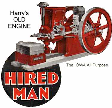
Old type (below #161150) straight trip finger and Hired Man brass tag. INSTRUCTIONS FOR OPERATING IOWA "OVER SIZE" GUARANTEED POWER ENGINES (Manual No. 140)Before Starting EngineBefore starting the Iowa "Over Size" Engine, see that nothing is broken or damaged. Take hold of the flywheels and turn them slowly by hand to make sure that everything operates freely. See that the governor balls, governor lever, igniter and tripping device, also the valve lever and valve springs, are in good working order. Oiling and CleaningFill the lubricator with a good grade of gasoline engine cylinder oil. This is very important. Turn up the little brass lever on the top of the lubricator and the oil will drop down through the sight feed glass. Adjust lubricator to drop about ten to fifteen drops a minute. This can be done by screwing the knurl nut on top of the lubricator UP or DOWN. Screwing the nut UP causes the lubricator to drop more rapidly, and screwing it DOWN, more slowly. Oil all of the working parts of the engine, such as the gears, governor lever and collar, side bar bracket, valve stem and valve lever. Fill the grease cup with a good grade of grease and turn the cap down so that there will be a pressure forcing the grease into the bearings. To fill the grease cup unscrew the cap and fill before putting it back into place. If it does not have an automatic feed this cup should be given one-half turn several times during the day's work. The grease cup on the end of the connecting rod is of the compression feed style. It is operated by a spring which forces the grease into the bearings. If the grease should become hardened, the cup may not work properly. Drop some lubricating oil on the crank shaft bearing before starting the engine, to be sure that it is well lubricated. Also drop a few drops of oil in the hole in the cam gear and on the end of the piston which extends out beyond the cylinder. To get the best service, the engine should be kept clean. Remove all the surplus oil and grease with a piece of cloth. Magneto OilingThe magneto should be oiled every other day when the engine is doing heavy work, with only one drop of good oil on each side. If the engine is doing light work or working only a few hours a day, you will not have to oil the magneto more than once a week. Do not put too much oil on the magneto as it has a tendency to stop the production of electrical current. (For magneto adjustment see a later section.) Cooling System and OverheatingThe cooling system of the engine consists of a hopper or water pot located on top of the cylinder and connected to the water jacket which surrounds the cylinder and its head. The water space and hopper should be filled with clean water (rain water preferred) to a point about three-fourths of the capacity of the hopper. The engine will work best. when the water in the hopper starts to boil, because this is the temperature at which any engine develops its maximum power. The water should be replaced frequently and the water pot kept about three-fourths full. Never allow the water line to go below the top of the cylinder. In cold weather it will be necessary to drain the water out of the engine by simply unscrewing the plug in the bottom of the cylinder or by opening the valve if there is one located there. Starting Iowa Chore Boy, 2 H. P.; Hired Man, 2 1/2 H. P., and Three Mule Team, 3 1/2 H. P. Engines
The engine is now ready to run up to speed and deliver its full power. See that the oil is dropping evenly from the lubricator, that the gasoline tank is filled with gasoline and the water pot is three-fourths full of water. On the Air-Cooled engines be sure that the belt is driving the fan up to its full speed. AdjustmentsAll parts of "IOWA" Engines are property adjusted and the engine is carefully tested on its own power before shipment from the factory. By following the foregoing simple suggestions, the engine can be started and operated without difficulty. In case readjustment becomes necessary later on, the following suggestions are given for the benefit of the user. Igniter AdjustmentA large percentage of gasoline engine trouble being due to faulty ignition. the following suggestions are given to help overcome them: Remove igniter from the engine and attach the wires from the batteries. Connect the switch and snap the igniter by hand and you should get a good hot spark at the contact points. If the batteries are weak or the igniter is short circuited, there will be a weak spark. To determine whether there is a short circuit in the igniter or in the batteries, disconnect one wire and brush it against the exposed part of the other wire, and notice the intensity of the spark. Remove all carbon or soot around the igniter points and the mica insulation, and brighten the contact points with sand paper. Turn the wheels over slowly until the igniter snaps, which should take place when the crankshaft is at an angle of ten to twelve degrees below its inner (lead center. A very simple adjustment is provided for changing the timing when necessary. To ADVANCE the spark, turn IN on the adjusting screw on top of the igniter pick bracket, first loosening the lock nut. To RETARD the spark turn this adjusting screw OUT. Be sure the lock nut is- SECURELY TIGHTENED after such adjustment. The igniter points should separate about one-sixteelith (1/16) inch. If natural wear causes more clearance, proper adjustment can be made by loosening the hammer stop clamp screw and turning the movable electrode to proper position. If points are worn uneven, they can be squared up by the use of a smooth, flat file. When operating the IOWA Engine on batteries, the igniter points Should be held apart by small coil spring attached to the igniter hammer stop and to the left hand post on the igniter body. There are two of these posts, one on either side of and just below the movable electrode, which electrode comes through the center of the igniter body. Either the "open" or "closed" post of the igniter points can be used for operating engine on magneto. However, the "closed" post is generally better for magneto ignition. This "closed" position is obtained by changing the spring from the left hand post to the right hand post. Exhaust Valve AdjustmentTurn flywheel slowly and see that the exhaust valve opens when the crankshaft is at an angle of 40 or 45 degrees above its "outer" dead center. By screwing IN the adjusting screw in the end of the valve lever, the valve will open EARLIER and close LATER. By turning this adjusting screw OUT, the valve will open LATER and close EARLIER. There should be a clearance of about 1/32 to 1/10 of an inch between the end of this adjusting screw and the end of the exhaust valve stem when the engine is compressing its charge-perinitting the valve to fit squarely into its seat. Check ValveThe check valve in the gasoline supply pipe between gasoline tank and mixer is intended to hold the gasoline back when the throttle valve is open and the engine is not drawing in a charge. Should some foreign substance get In the seat of this valve, it will be necessary to remove and clean it. Be sure, when supply pipe is again connected, that check valve has not been put on backwards, in other words reversed. Gasoline Mixer AdjustmentWhile the engine is running, open throttle or needle valve in the gasoline mixer until the engine starts to miss explosions or shows other signs of weakness, and notice the number on the dial near the wire indicator. Now close the throttle until the engine starts to miss explosions and notice the number on the dial. About hall way between these two numbers will give the "right" adjustment. Black smoke coming out of exhaust pipe indicates too much gasoline. Missing, followed by a sharp explosion, indicates not enough gasoline. Governor AdjustmentIf a slight change of speed is desired, regulate the adjusting screw which passes through the governor lever, turning it IN to increase the speed, and turning it OUT for slower speed. Turning UP the eye-bolts attached to the governor balls will give additional speed, and unscrewing these bolts will give less speed. Attached to governor lever and side bar will be f ound two sharp-edged steel plates, through the proper working of which the governor balls regulate the power and speed of the engine. These plates or blades should have a clearance of 1/32 of an inch, both endwise and sidewise, and the edges should always be kept sharp and true. When broken or worn, these blades should be replaced. The governor must work freely without sticking. A drop of oil on the knife-edged blades will keep them in good condition. Stopping the Engine
CautionsKeep the water pot half or three-quarters full of water. Never allow the water to get below the joints of the water pot on the cylinder. WATERCOOLED ENGINES RUN BEST WHEN THE WATER IS BOILING. The four principal causes of trouble on a gasoline engine arise from Poor Ignition, Loss of Compression, Poor Lubrication and Loose Bearings. Of these four the last one must be guarded against most carefully. Just as soon as an engine bearing gets loose and begins to pound, it should be looked after, removing enough of the shims to take up the wear. If this is not done, the engine will rack itself to pieces. It is a good idea to look any engine over thoroughly each time before starting to make sure the bearings are properly adjusted. This is especially true for the connecting rod bearings in a gasoline engine. BE SURE AND KEEP THE ENGINE WELL OILED. Associated Alternating Current MagnetoSome Magnetos that are designed for farm engine use do not produce a continuous (DC) electric current. In these, there are only two points in each complete revolution of the armature that it discharges its maximum electric current. It is therefore necessary
to time the magneto so that one of these points is reached just at the time the igniter snaps. IMPORTANT: Before touching the magneto or endeavoring to make any adjustments see that the igniter is set for the proper
firing point. Just as the Igniter trips, the correct position of the crank shaft for the "Chore Boy" engine is 15 degrees below inner
dead center. This angle varies from 10 to 30 degrees depending on the speed of the engine and the length of the stroke. CAUTION: Never touch the magneto until you are sure that engine is property timed and the igniter, and igniter points
are clean and adjusted. See that the mica insulation is not burned out. It is a good plan to wash the igniter thoroughly in kerosene.
After these instructions have been carried out and it is then found necessary to time the magneto, follow the instructions below. Timing Magneto
FIRST: Note the direction the magneto gear turns when the engine is running. By referring to the illustration of the magneto, you will note there are two small PUSH BUTTONS, one marked "L" and the other marked "R." If the magneto gear (marked M. G.) turns toward , the letter "L" the push button near letter "L" is to be used. If the gear turns toward the letter "R," the button
near "R" is to be used. SECOND: Stand on the igniter side of the engine, turn the flywheels in the direction the engine runs, stopping instantly when the igniter snaps and do not allow the wheels to turn. CAUTION-Be sure engine is "firing" at proper time, otherwise you are likely to make the engine run worse rather than better. THIRD: Loosen the screws that hold the magneto to the magneto bracket, then raise the magneto high enough to lift the gears out of mesh. FOURTH: Then turn the magneto gear in the same direction you found the magneto gear (marked M. G.) running when the engine was turned over. If the magneto gear runs toward the letter "L," press in on the push button near letter "L" and turn the magneto gear until you feel the PUSH BUTTON enter a slot in the inside mechanism of the magneto. Hold this PUSH BUTTON in and lower the magneto so that the gears are again in mesh and tighten the screws that hold the magneto to the bracket. PLEASE NOTE: If you find the magneto gear (M. G.) turns towards the letter "R," use the PUSH BUTTON near the letter "R" following the same timing instructions as above. TIMING OLD STYLE MAGNETOS. On some of the old style magnetos the magneto gear was fastened to the magneto shaft by a set screw, only there was no idler gear. In this case it is not necessary to loosen the four screws that hold the magneto to the magneto bracket, but just loosen the screw that holds gear and remove it from the magneto shaft. This will allow you to turn the magneto shaft without raising the magneto from the bracket. Use the same timing instructions as given above. |
CLICK HERE to buy books about Gas Engines
There's a WHOLE LOT more to this site so click and cruise around!
![]()
| ENGINES | SHOWS | SEARCH | SUPPLIERS | IGNITIONS | ABRASIVES | CLASSIFIEDS | BOOKS |
SCRAM back to Harry's Page!
Page!
![]()
Published by Harry F. Matthews © 1995 - 2000. ALL RIGHTS RESERVED!