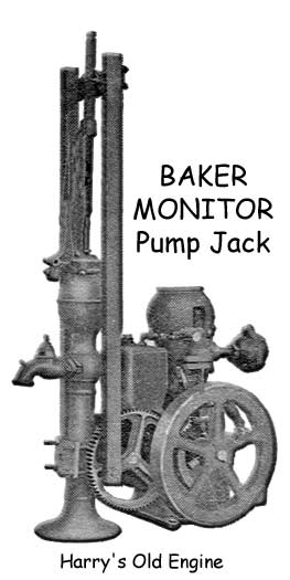
Harry's Old Engine #19
Little Monitor 1-1/4 HP Gas Engine Pump Jack
Have fresh water when you want it.
The Little Monitor water pump is a standard four cycle engine with jump spark ignition, hit and miss governor, and the following special features.
COOLING:Hopper cooling is used, because air-cooled engines at full load are not properly cooled. In the latter type the lubricating oil burns from the piston, resulting in high friction, rapid wear, waste of power, and excessive use of gasoline. Then again heavy gasoline is cheaper and a gallon gives more power, but with it engines do not start so easily in cold weather. Pouring hot water into the hopper is the most convenient way to warm up an engine. It is desirable to warm an engine, not only to help evaporate the gasoline, but to limber it up. Zero weather makes an engine stiff, and crank hard. CLOSED CRANK CASE: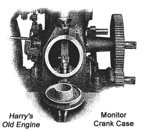
Many engines have open crank cases, exposing the principal working parts. Dust freely enters, and works its way into the bearings and cylinder, causing unnecessary wear. More or less oil is thrown from the engine to fall on surrounding objects. In time the engine actually becomes the center of filth. No such charge can be brought against the Monitor, for the crank case is entirely closed, protecting the working parts inside. The hand-hole opening shown in the accompanying cut, affords easy access to the connecting rod, for adjustments. This opening is effectually closed by a hinged cover with machined joint and gasket between it and the crank case. CRANK SHAFT:A drop forging of liberal dimensions is used for this extremely Important part. Few engines of the same horsepower have cranks as large. Besides giving additional strength, a large sized shaft distributes the force of the explosion over a large bearing surface-reducing the pressure per unit of bearing area and prolonging the life of the bearings. By placing the pinion outside the main bearings, and by using a drop forged crank shaft instead of a bent shaft, the main bearings are brought very close together, giving additional strength to the crank shaft. CONNECTING ROD:One of the most vital parts of an engine is the connecting rod. It moves rapidly and reverses its direction 1,000 times per minute. A looseness of 1/200 of an inch in the crank bearing will cause a knock which, if not remedied at once, will grow rapidly worse and be the cause of great damage. To make an adjustment of 1/200 of an inch in the ordinary two-bolt type of connecting rod, having shims, is a difficult matter. The thinnest tin is 1/50 of an inch thick, or four times the thickness which must be removed to take up an objectionable looseness in the bearing. If a single tin shim be removed and the bearing bolts tightened, the bearings will heat, while if the nuts are left a little loose to prevent this, they are liable to loosen more. 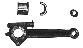
To overcome these difficulties Baker adopted a hinged cap for the crank bearings and use but one bolt. Shims have been eliminated altogether. The bolt has a T-head which prevents it from turning and two nuts which are easily accessible through the crank case opening. One nut is deeply notched to allow locking it in position by passing a cotter-pin through the bolt. This gives an absolute lock for the nuts. When the two nuts are locked together in this way, the threads do not wear. By simply removing the cotter-pin and turning the nuts, adjustments as small as 1/200 of an inch can be made quickly, and all parts left absolutely rigid. CYLINDER AND WATER TOP:The cylinder and water top are one casting, but separate from the crank case. By uncoupling the gasoline pipe and removing two nuts, the cylinder may be taken from the crank case and the piston examined. The water space around the cylinder tapers down to nothing at the bottom, insuring the jacket water freezing at the bottom first. When the jacket is not more than one-half full of water the engines may be frozen without cracking the jackets. GASOLINE TANK:Baker made the fuel tank of cast iron, because it will not rust through and has no seams or flanges to spring a leak. In case of a blaze near the engine, it is the safest kind of a tank for it has no joints to unsolder, will heat up slowly, and will withstand great gas pressure from within. It is strongly bolted to the crank case with its top just below the throttle, so that the gasoline cannot drain from the tank through the throttle into the combustion chamber. CHECK VALVE IN FUEL SUPPLY PIPE:On the suction stroke the inrush of air past the throttle point, sucks the gasoline up and thoroughly atomizes it, before it enters the cylinder. In order to conserve gasoline and to get the most power from it, the air and fuel must be thoroughly mixed, and in the right proportions-neither too much nor too little gasoline. A check valve in the auction pipe holds the gasoline up to the point of the throttle. This is very important (but omitted by many builders), and when omitted the gasoline stands in the gasoline pipe at the same level as the tank. Air is first drawn into the combustion chamber and then gasoline, instead of a mixture of air and gasoline, throughout the stroke. After idle strokes, for governing, the first suction charge has too little gasoline and those which follow immediately are too rich in gasoline. For economy of operation buy an engine having a check valve in the gasoline supply pipe. VALVES AND VALVE CAGES: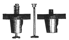
Both intake and exhaust valves have cast iron heads, electrically welded to carbon steel stems. The cast iron heads stand the heat better than steel and the electric weld is superior to any other joint. The intake valve seats on the cylinder casting and the exhaust valve is placed in a separate valve cage with a long tapering body which is ground to fit a corresponding opening in the cylinder. This construction eliminates the use of gaskets, thoroughly cools the exhaust valve and provides an easy means of getting at either valve for inspection or regrinding. BEARINGS:Large sized bearings will be found throughout the engine and replaceable bushings are used at both ends of the connecting rod, as well as in the cam shaft and jack shaft bearings. The main bearings for the crank shaft are babbitted. The crank end of the connecting rod contains a set of die cast bushings made from a special grade of babbitt which has extremely durable qualities, yet it is not hard enough to score the crank wrist-pin. The piston-pin bushing is made of Tobin bronze, a material known for its excellent wearing qualities. LUBRICATION:No simpler or more reliable system of thoroughly lubricating a gasoline engine has ever been devised than the one used on the Little Monitor. On the inside of the crank case cover there is a little cup holding one-tenth of a pint. Filling the cup with lubricating oil and emptying It Into the crank case each time the gasoline tank is tilled is all there in to do to thoroughly lubricate all the important parts. There is no funnel to find, no sight feed oiler to fill, watch and adjust, no grease cups to fill and screw down. 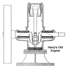
The area of the surface of the oil in the crank case is large, and the cup of oil raises the oil level only 1/16 of an inch. Hence the depth of the oil in the crank case remains practically constant and the quantity of oil being splashed into the bearings is not perceptibly increased by putting a cupful of oil into the crank case. The accompanying diagram shows the lower part of the crank case. A substantial knife shaped projection on the cap of the connecting rod splashes the oil into the connecting rod and cam shaft bearings, and onto the piston, cylinder, and wails of the Frank case. As it drains from the latter, it is caught in cups and conducted into the main bearings. After passing to the outer ends, the oil is thrown away from the shaft by the flanges into circular cavities in the outer ends of the bearings. From here it drains through large tubes back into the crank case to be used over and over again without waste. The crank shaft actually runs in a flood of oil, a condition accepted by all authorities as furnishing almost ideal lubrication. Durable and easy running bearings are the result. Briefly, the system thoroughly lubricates all the large and important friction surfaces using the least possible amount of oil, prevents oil being thrown from the engine, keeps the oil supply clean, does away with oil and grease cups, requires less attention than any other system, and to much more reliable. DRIVING CREAM SEPARATOR:The cam shaft is driven one-fourth as fast as the engine by a well guarded, cut gearing, with one inch face. The gear is cast iron, and the pinion steel. A pulley may be put on either shaft. The 4 1/2 - inch friction pulley on the cam shaft, which turns 125 revolutions per minute, will drive most cream separators at the proper speed. This pulley will start a separator slowly, increase the speed gradually and run it without jerks at all times. GOVERNOR:For operating a cream separator or other machine where a uniform speed is necessary, this engine gives excellent satisfaction. It uses a hit and miss governing device, similar to those used on the large engines-just as sensitive-just as reliable. The governor weight is placed some distance from the fly-wheel hub, where it moves very rapidly and responds quickly to any change of speed. The heavy fly-wheel of large diameter, also aids materially in securing a uniform motion. DETACHABLE PUMP GEAR:The pumping gear used on the LITTLE MONITOR connects the engine proper with the pump. On one side, the frame of the gear bolts to the main frame of the engine while the other side clamps to the pump standard. The gear itself Is driven by a pinion on the slow speed shaft of the engine and transmits its power through a pair of wood pitmans, to the pump rod. Both engine and pump, act as a single machine. There are no belt troubles and the drive is always positive. When the engine is wanted at some other point the pump gear can be easily detached and left clamped to the pump, ready for work as soon as the engine is returned to its original position. The three point bearing between the pump gear and the engine frame, allows for adjustment of the gear, to compensate for wear. THROW OUT DEVICE:A valuable improvement in the LITTLE MONITOR consists of an eccentric sleeve or bearing for the pump jack shaft. This bearing turns in the frame of the pump jack throwing the pump jack gear into mesh with the drive pinion on the engine, or disconnecting the gears. As the gear can be readily shifted while the engine is running, the operator can start the engine without load. This Is a big advantage when the engine is pumping a deep well, or is used during very cold weather. Throwing out the jack, also, makes the engine ready for belt work without any changes in the setting. EQUIPMENT:Each engine is furnished with a water-proof battery box, armored with galvanized steel, and containing four dry cells spark coil, and wrench. A four and one-half inch cast iron pulley with flange is also part of the regular equipment. Parts Drawing: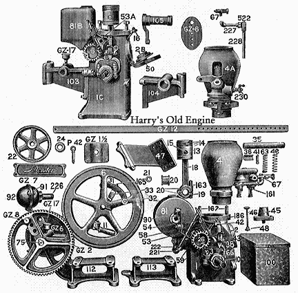
As restoration begins, photos will be added to this text. Text courtesy Baker Manufacturing Company, Evansville, Wisconsin 3-26-1930. Please visit our sponsors on the Business Card Page |
There's a WHOLE LOT more to this site so click and cruise around!
| ENGINES | SHOWS | SEARCH | SUPPLIERS | IGNITIONS | ABRASIVES | CLASSIFIEDS | BOOKS |
SCRAM back to Harry's
 Page!
Page!Published by Harry Matthews © 1995 - 2007. ALL RIGHTS RESERVED!