International Harvester
2HP Titan Vertical
Hit and Miss Engine
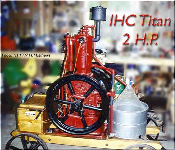
Restored by Charles R. Bryant of St. Peters, MO
From the IHC manual...DESCRIPTION OF ENGINEThe I H C vertical engines are of a type known as the "four-cycle," and operate on gasoline, gas or alcohol. The engine derives its power from expansion resulting from the burning of a mixture of a fixed gas or of some inflammable vapor and air, compressed at one end of its cylinder. 
Referring to Figures 1 and 3, showing an International vertical engine with all of its important parts named, the piston being in its extreme upward position. On the down stroke, the mixture of gasoline and air is drawn into the cylinder, through gasoline mixer and inlet valve, the amount of gasoline being regulated by the needle valve. On the return upward stroke this mixture of gasoline vapor and air is compressed, and a little before the end of the stroke is ignited by an electric spark. The burning of the gases causes an increased pressure and forces the piston rapidly on its second downward stroke. Near the end of this downward stroke the exhaust valve is opened by means of the exhaust valve lever operated by a cam. On the second upward stroke the burnt gases are forced out of the cylinder through the exhaust valve opening. This completes one operation, which, it will be noticed, requires four strokes of the engine, from which the engine derives the name of a "fourcycle" engine. This operation is repeated until the engine has reached its maximum speed, when the governor, acting through a detent, holds the exhaust valve open and locks the inlet valve, thus preventing the combustible mixture from entering the cylinder. The operation of the ignitor is stopped while the exhaust valve is held open. The governor holds the exhaust valve open and locks the inlet valve only when the speed of the engine is above normal. As soon as the engine returns to its normal speed, the detent releases the exhaust valve, and the engine again operates as has been described. GASOLINE AND GASOLINE MIXER
Use ordinary gasoline, having a specific gravity of not less than 65 Degrees Baume. The needle valve head is marked "1" and "2" The valve is opened so that the mark "1" is on top for starting the engine. As soon as the engine takes an explosion, the valve is closed, so that mark "2" is on top. This, however, will vary slightly. A few trials, with close observation of exhaust, will determine the proper amount of fuel. Too little gasoline results in a loss of power and an occasional explosion in the suction pipe. Too much gasoline gives a dead explosion and black smoke in the exhaust. Should the engine be flooded with gasoline, the charge will not ignite. In such cases the gasoline must be shut off and the engine turned over several times to work out the excess of fuel. This is easily done by holding one of the valves, preferably the exhaust valve, open while turning the engine over. Flooding of the engine is often the cause of. the engine not starting. Be sure that the gasoline mixer is properly filled with gasoline, that the needle valve is properly opened, and that the switch is closed; also close the starting damper in air pipe. (As soon as engine starts this damper must be opened.) The engine should then start readily. IGNITOR AND IGNITION
"Make-and-break" ignition is used. The ignitor consists of a stationary insulated electrode and a movable electrode, mounted together in a plug that is arranged to extend into the combustion chamber of the engine, as shown in Figure 3. The contact points are of special alloy, to insure good electrical contact and long life, this alloy not being subject to corrosion or to oxidation from the hot gases. The contact points are held apart by the ignitor hammer spring until the valve rod is moved upwards by the cam. The ignitor trip engages the ignitor 'hammer, raises it against the tension of the ignitor hammer spring and the hammer stop spring, revolving the movable electrode until the contact points come together, thus completing the electric circuit between the two electrodes; the hammer is then carried a little higher and tripped, separating the contact points with a snap and producing a good spark. One battery wire is attached to the insulated electrode and the other to the engine frame. It is very important to have the ignition take place at the proper time of the compression stroke. For a speed of 400 revolutions per minute, the ignitor hammer should trip off as the spokes on line A B, Figure 1, are straight up and down on the line A'B',the engine being turned slowly by hand in the direction of the arrow. For slower speed, the ignitor hammer should trip off a little later, that is, after the spokes have passed the vertical line A' B'. The adjustments for "timing" the ignition are made by raising or lowering the ignitor trip on the valve rod. Raising the trip makes the ignition earlier. The adjustment is further effected by swinging the trip roller support towards or from the trip. In making any change in the timing adjustment of the ignitor, be careful not to lower the trip too low, for then the length of time of contact may become too short to give time for the battery to establish a good flow of current through the spark coil. This would result in a very poor ignition. Figure 4 shows the ignitor trip and the ignitor hammer in correct position when valve rod is at its lowest point. To determine time of contact, raise the ignitor hammer gently until you feel the points inside the cylinder just come together. Then slowly turn the engine until trip touches the hammer. Note the position of some spoke in the fly-wheel, then again turn engine until ignitor trips, when the spoke following the one noted should be, or nearly so, in the position noted at the time of contact. In other words, the fly-wheel should have revolved approximately the distance between two spokes, or 60 degrees, while points are in contact. If engine fly-wheel revolves more than 60 degrees during the time of contact, lower the trip a little and, if necessary, swing trip roller support toward the trip. If the flywheel revolves less than 60 degrees, raise the trip, but NEVER closer to the hammer than A of an inch. When valve rod is in its lowest position, make proper adjustment on the trip roller to trip at the proper period. Be sure that all bolts and nuts are tightened up before starting the engine again. The sparking points can be cleaned by lifting up on the ignitor hammer so that the sparking points come together, and pushing in on the movable electrode several times. This has the effect of sliding one point upon the other-cleaning them. However, the ignitor plug should be removed and cleaned thoroughly every week or ten days. BATTERY AND BATTERY CONNECTIONSThe battery is a very important part of the engine, and should be inspected to see that all wire connections are tight. A weak battery gives poor ignition, and results in a loss of power and the use of more fuel. By keeping the strength of the battery up, a waste of fuel and trouble from delay in starting of engine will be avoided. It is well to test the circuit and spark occasionally. To do this, close the switch, take a wire and touch both electrodes at the same time, making and breaking the connection. If there is no spark, look for a broken connection from engine through the batteries and spark coil. See that all connections are clean and tight. No spark should occur at the switch when turning off or on, except when the trip has raised the ignitor hammer high enough to bring the contact points together. If a spark occurs, at any other time, or when hammer is down as shown in Figure 4, there is a short circuit, and no spark will occur in the combustion chamber, and the batteries will run down quickly if the switch is left on. See that the wire leading to the insulated electrode does not touch the engine. Having examined this thoroughly, should the short circuit remain, disconnect this wire from the insulated electrode. Now close the switch and connect the wire with some uninsulated part of the engine, first making sure that the contact points inside the engine are apart. You should get no spark. If a spark occurs, the ignitor should be taken out and thoroughly cleaned. OILINGAlways oil the engine before starting up. Use standard gas engine oil in the crank chamber and in the cylinder lubricator. Adjust the lubricator to feed from three to five drops per minute. Too little oil results in a hammering noise in the cylinder, reducing the speed and loss of power. Too much oil is indicated by a bluish smoke at the exhaust. The ignitor and all moving parts should be frequently oiled with gas engine oil. Use the best of grease in the grease cups. If there is an indication, at the exhaust of too much oil, drain a little from the crank chamber, but always leave enough so that the oil dipper reaches into it and splashes oil on the drain surfaces of the handhole cover. It is well to have just sufficient oil In the crank chamber, so that it will show on the drain surfaces adding a little whenever the amount of oil splashed up diminishes. The inside of the crank cbamber should be cleaned out occasionally, as a sediment will collect and mix with the oil and also decrease the capacity of the chamber. When there is a small quantity of oil in the crank chamber, the oil becomes frothy and will collect on the inner walls of the chamber instead of circulating and lubricating the engine parts. VALVESThe valves should work freely. If the stems are gummed, use a little kerosene or gasoline to loosen them up. The valves should seat tight at all times. Leaky valves mean loss of compression and loss of power. By turning the engine over on compression stroke and listening carefully for escaping air, a leaky valve may easily be found. If a valve leaks, it must be reground, unless the leak was caused by dirt under the valve seat. To regrind a valve, place oil and flour of emery upon the seats and revolve the valve on its seat, pressing firmly and lifting the valve occasionally. After a good seat is obtained, be sure to wash off all emery and oil from the valve and seat with gasoline or kerosene before replacing them. GASKETSAll joints and connections subject to heat are packed with asbestos gaskets. If the gasket is torn in removing it from any part, a new gasket must replace it. Cut this gasket very carefully so as not to break it. Use sheet asbestos or "Mobilene" packing that is even and not broken by folding. It should be about 1/32 of an inch thick. Before placing new gasket, remove all parts of old one. In tightening the bolts, tighten them uniformly and go over all bolts as soon as engine has been warmed up. DEPOSITS IN EXPLOSION CHAMBERWhen an engine has run for many months, an examination will show a tarry deposit in the explosion chamber. This should be carefully removed from time to time. It is the result of a poor gasoline or too much fuel. When removing this deposit, the valves, ignitor, piston and piston rings should also be cleaned, washing them thoroughly in kerosene and oil before replacing them. Keep all grit and dirt out of your cylinder and piston rings. Examine the water jacket of the cylinder and cylinder head, as different waters form lime-like deposits. This can be removed with a chisel or rod and a strong solution of soda. The above is important in that the deposit of lime in the water jacket causes the engine cylinder to overheat. GEARSThe small gear or pinion on the crankshaft has one tooth directly over the key-way marked, which meshes with two marked teeth on the large gear. If these gears are removed for any reason, they must be replaced in their original position. GASOLINE PUMP AND CHECK VALVESShould the gasoline pump fail to pump oil to the mixer, examine the check valves thoroughly. Remove all dirt from pipes. Rapping the check valves lightly with a hammer, will sometimes put them in working order. If the seat is corroded, it should be ground in the same manner as the engine valves, using a very light pressure. The packing on the pump plunger must be renewed occasionally. This can be done with candle wicking, which is the best packing for resisting the action of gasoline. Do not use rubber, as gasoline will dissolve it. To repack the pump, remove the pin above the spring washer by pressing down on the spring and washer, unscrew the nut and remove the gland, wind candle wicking around the plunger and pack evenly. Be sure to oil the pump plunger when starting the engine, and occasionally during a long run. This will save the packing. NOTE: These engines can be started without the use of a starter crank. To do this, hook up the cam lever as usual, pump up the gasoline, open the needle valve, but do not close the switch. Next lift up the starting damper and turn the engine over once to draw in a charge. Now close the switch and swing the fly-wheel backwards until the ignitor is tripped. If a proper mixture has been drawn into the cylinder, the switch turned on, and no load on the engine, it will start. With a little practice you should be able to start your engine easily. |
There's a WHOLE LOT more to this site so click and cruise around!
![]()
| ENGINES | SHOWS | SEARCH | SUPPLIERS | IGNITIONS | ABRASIVES | CLASSIFIEDS | FORUM |
SCRAM back to Harry's Page!
Page!
![]()
Published by Harry F. Matthews © 1995 - 2021. ALL RIGHTS RESERVED!